Installation
Install Software
The AFM Software Suite is installed with a standard installer. When you install the software, you agree to the terms of the IMP license. The IMP software Suite can be run on the same computer as the host AFM, or on a separate computer. It is advantageous to run the AFM Suite on a modern computer with a multi-core processor, especially when analyzing full images to make Parameter Maps.
If the AFM Suite does not detect the The Multifrequency Lockin Analyzer™ (MLA™) upon starting, it will open up in analysis mode. In analysis mode you can plot and analyze data taken previously, but you can not take data. You are free to install the software on as many seperate computers needed to analyze your data. To take data you mast start the IMP Suite when connected to the MLA™ and a host AFM, as described below.
Install Hardware
Connecting the hardware the first time requires some effort. However, if things are configured nicely, one or two hardware switches is all that is needed to switch between the normal configuration of your host AFM and the ImAFM™ configuration. The MLA™ is connected to the host AFM via a signal access module (SAM) provide by Intermodulation Products or your AFM supplier. The MLA™ is connected to a computer running the AFM Suite via Ethernet, either the same computer used by the host AFM, or a seperate computer.
Connection to computer
The AFM Suite will open analysis mode when it does not detect an MLA™ connected to the computer. To establish the connection between the computer and the MLA™ you must first perform the steps below. After this procedure the detection will be automatic. The instructions given below are for Windows 7.
Connect a standard Ethernet cable between the MLA™ and the computer.
Go to
Control Panel->Network and Internet->Network and Sharing Center.Locate the network adapter: In the left panel choose
Change adapter settings. To identify which adapter corresponds to the Ethernet card connected to the MLA™, turn off the MLA™. There should be a red cross on the adapter icon with the textNetwork cable unplugged. About one minute after the MLA™ is turned on the red cross will disappear and the text changes toUnidentified network.Configure the MLA adapter: Right click again on the MLA adapter and choose
Properties. SelectInternet Protocol Version 4 (TCP/IPV4)and clickProperties. ClickUse the following IP addressand fill in the followingIP address: 192.168.42.1
Subnet mask: 255.255.255.0
Check the adapter: At this point the internet connection between the MLA™ and the computer should be established. To test the connection you can ping the MLA™. In a Windows terminal window type
ping 192.168.42.50. The MLA™ should respond with something like:Pinging 192.168.42.50 with 32 bytes of data:
Reply from 192.168.42.50: bytes=32 time=1ms TTL=128
Connection to host AFM
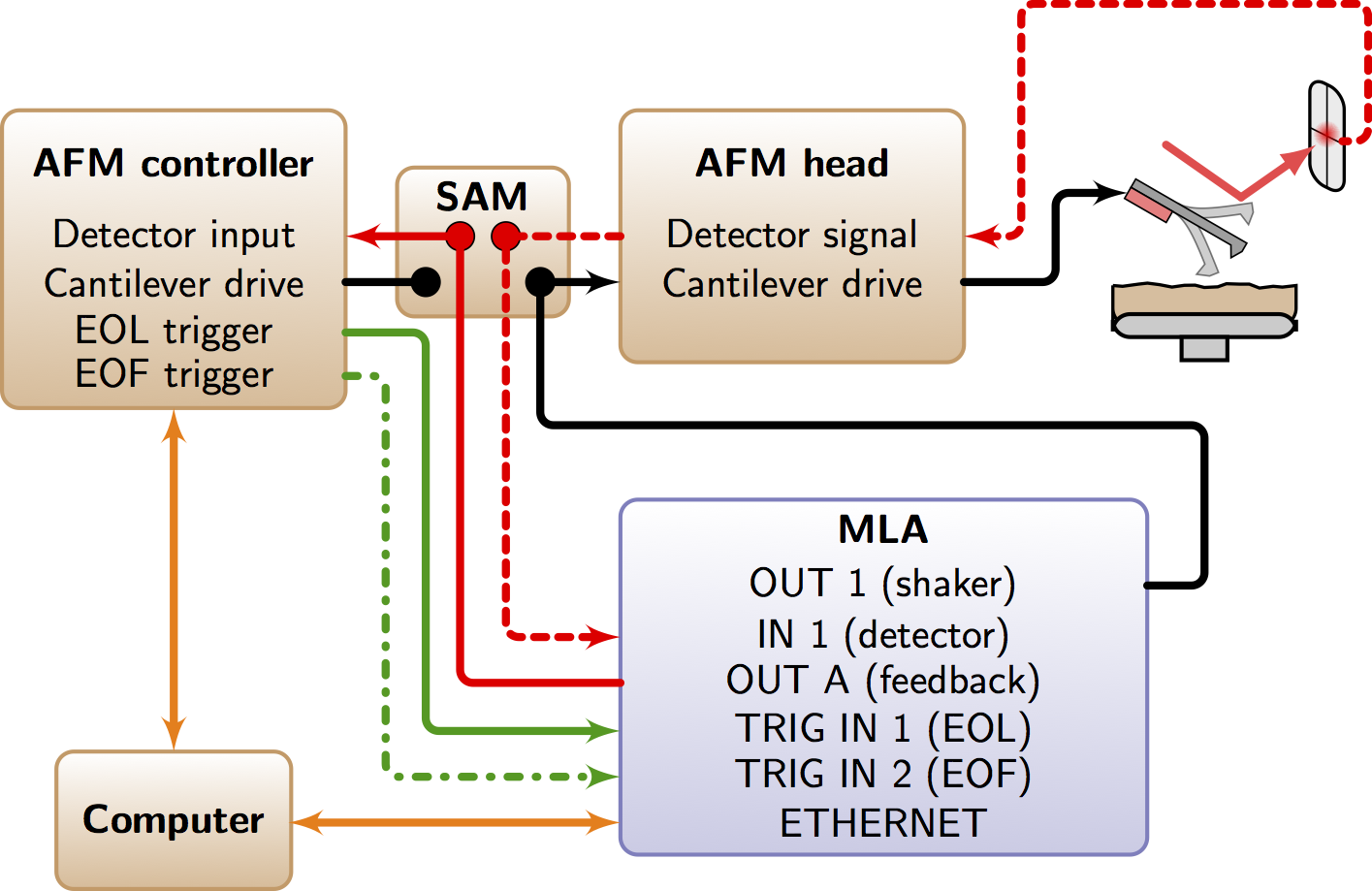
The general connection scheme is shown the diagram above. The cantilever drive, detector, feedback and trigger signals must be routed through the MLA™. This routuing may be with with BNC cables to the font pannel of the MLA™, or with a composite cable to the AUX connection of the back panel of the MLA™. On some AFMs a separate Signal Access Module (SAM) is required. Intermodulation Products provides dedicated SAMs for a few common AFMs to easily toggle between the normal function of your host AFM and ImAFM™. On other AFMs, notably Asylum and JPK, one connects BNC cables directly to the controller and changes signal routing using software activated switches. You can get a script from Intermodulation Products to automatically perform the signal routing. Detailed instructions are given below for different AFM’s. Contact Intermodulation Products to find out what solutions exist for your particular AFM <info@intermodulation-products.com>.
Set AFM Type
In the AFM Suite, under the Advanced pull-down menu, select Setup AFM. A dialog box appears with a pull-down menu to choose your AFM type. This option will only appear when the IMP Suite detects the MLA™ and starts in full mode, ready for taking data. The settings for the various AFM types are stored in the folder IMP Sessions and Settings/settings/configurations. These files contain information about triggers, over-scan factors, and more. Advanced users can use the files in this folder as a template to make their own custom_afm.ini settings file. When the software is restarted, a new custom_afm settings will appear as a choice in the pull-down menu.
If your AFM type does not have a configuration file, contact Intermodulation Products for help in making a custom configuration file <info@intermodulation-products.com>.
Working without triggers
Nearly all AFM’s have some kind of access to the end-of-frame (EOF) and end-of-line (EOL) triggers. If the EOF trigger does not exist, it is still possible to manually start the ImAFM™ scan when the host AFM scan starts. However, after several scans a manual restart is needed to re-sync the frames. If the EOL trigger does not exist, it is also possible perform ImAFM™ but in this case one needs to accurately adjust the timing in order to keep ImAFM™ in sync with the host AFM.
Under the Advanced pull-down menu, select Setup AFM. Two fields appear in the AFM Setup dialog. The Line frequency should be set to the frequency at which you want ‘fake’ EOL trigger signals to come. The Delay is the number of pixel time intervals the MLA™ will wait after the ‘fake’ EOL trigger, before it starts to record a scan line. Setting both of these fields to zero causes no ‘fake’ EOL signal to be generated, and in this case the AFM Suite relies on the trigger signals recived by MLA™. These two fields should be set to zero when running with external triggers from the host AFM.
Common AFMs
Nanoscope TM III, IIIa, IV
ImAFM™ works perfectly well with older Multimode and Dimension AFMs, originally developed by Digital Instruments (DI), then sold by Veeco and currently by Bruker. These are excellent AFM’s and there are many good instruments still in service. The upgrade to ImAFM™ is a good way to give these systems a second life and convert them to a modern AFM with the latest surface analysis capabilities. You do not need to upgrade to a NS-V controller and ImAFM™ performance is not compromised with the older NS-III and NS-IV controllers.
Access to the detector signal and cantilever drive are provided via a Signal Access Module (SAM) from Intermodulation Products. This gives you low noise and low cross-talk connection with the host AFM and one switch is all that is required to toggle between normal use of your AFM and ImAFM™. The SAM should be placed in between the microscope and the controller. If there is a Phase Extender Module with the NSIIIa controllers, you should place the SAM in between the microscope and the phase extender module. A general rule of thumb is: Place the SAM directly after the microscope, before the controller or any other ancillary equipment.
You can also use the SAM provided by DI/Veeco/Bruker, which gives access to many other signals, but has some cross-talk between signals which degrades performance, and it requires two switches to change between normal operation and ImAFM™. The actual connections on the DI/Veeco/Bruker SAM depend on which version you have, and which controller you are running. Consult your DI/Veeco/Bruker manual when making these connections. Contact Intermodulation Products if you have any troubles as we have found errors in some versions of these manuals. See SAM III connections for an image showing a typical connection.
The trigger signals on the NS-IV controller are accessible from BNC connectors on the back side of the controller. On the NS-III and NS-IIIa controllers they are accessible via BNC connectors located inside the controller box. You need to remove the lid to access these connections. If you would like a more clean solution, you can install connectors on the front of the controller. You need to remove the front panel and drill two holes for this installation. Intermodulation Products can provide the necessary cables and advice.
See Nanoscope III and IIIa Trigger Access for images and detailed instructions on accessing the trigger signals.
Nanoscope TM V
The NS-V controller is currently sold by Bruker for most of their AFMs e.g the Icon and Fast-Scan AFMs. If the NS-V is running a Multimode AFM, or Dimension AFM, the IMP-NS4-SAM gives you signal access. If the NS-V controller is running on a Multimode or Dimension AFM, you can use the same SAM as that for the NSIII and NSIV controller described above. If you are running a Bruker Icon, Fast-Scan, or other more recent AFM using the NSV controller, Intermodulation Products has a low noise SAM with access the vertical and latteral detector signals, as well as apply a voltage to the tip. If these connections are sufficient, you do not need the SAM-V module from Bruker. However, if you have the SAM-V, you can use it to make the connections. See Nanoscope V Connections for an image showing a typical connection. Contact Intermodulation Products if you would like a dedicated ImAFM™ SAM for the NS-V Icon or Fast-Scan systems.
Access to the trigger signals is on the front panel of the NS-IV controller. See Nanoscope V Connections for an image showing the access to the trigger signals.
software settings
With the NS-V controller and software v8 and later it is also necessary to configure the software to make the connections required for ImAFM™. In addition to setting the system to contact mode and setting the set-point to 0 Volts, you need do the following:
To get access to the shaker piezo when the Bruker is set to contact mode, go to the Microscope pull-down menu and select Generic Lockin. Select the tab for Lockin-1 and enable this lockin. Under drive routing select tapping piezo and set the amplitude to zero. Test the system and if it works, save this workspace as ImAFM.
For ImEFM you need to set the software as above, and configure for connection for the tip voltage. Go to the Advanced Settings menu (red stop-sign icon). Under the group other go to tip bias control and select the option tip bias. Also in this group go to sample bias control and select the option ground. Test the system and if it works, save this workspace as ImEFM.
Asylum MFP-3D TM
These systems can be found with the older MFP-3D TM controller, the ARC TM and ARC2 TM controller. With all of these controllers, signal access is via BNC connections on the front panel of the controller.
- Hardware connections:
OUT A on the MLA™ <-> In 1 on the controller.
OUT 1 on the MLA™ <-> In 0 on the controller.
IN 1 on the MLA™ <-> Out 0 on the controller.
- Signal routing is configured in the software cross-point switch and these settings are most easily made by running a script, or Igor Procedure file ImAFM_MFP3D.ipf supplied by Intermodulation Products, which allows you to toggle the between normal AFM and ImAFM with a GUI button. The cross-point connections can also be made by hand as follows:
user.alias.l (left column) <-> Deflection (right column).
user.alias.d (left column) <-> Input.fast (right column).
It is necessary to write the changes and Lock the cross-point
You can Read the changes in the All tab and check if Deflection is indeed connected to Input.fast.
NOTE: making these changes redefines the alias’s for all modes, and therefore Contact mode will not work as normal unless you switch back to the original settings, or restart the Asylum software. Make a note of what Deflection is set to before you make these changes manually.
The trigger connections require that you purchase a controller accessory from Asylum Research called the Digital Access Module TM (DAM). This module connects to a DIN connector on the front of the controller, it has BNC connections for:
Port 2 LINE on the DAM <-> TRIG 1 on the MLA™.
Port 3 FRAME on the DAM <-> TRIG 2 on the MLA™.
Asylum Cypher TM
The Cypher AFM runs the ARC or ARC2 controller. The signal connections can be made as with the MFP-3D, but it is preferable if they are made on the so-called ‘backpack’ of the Cypher itself. The signal connections are:
Output 0 on the Cypher backpack <-> IN 1 on the MLA™.
Input 0 on the Cypher backpack <-> OUT 1 on the MLA™.
Input 1 on the Cypher backpack <-> OUT A on the MLA™.
The signal routing is made as for the MFP-3D as described above, which is easily done by running the ImAFM_Cypher.ipf script.
The trigger connections with the ARC and ARC2 controller are done exactly as with the MFP-3D controller, via the Digital Access Module TM.
JPK Nanowizard TM III
The connections to the JPK Nanowizard III are shown here: JPK Nanowizard III Connections.
As with other systems, ImAFM™ is done with the JPK software in contact mode. Run the IMP-JPK script to open a small GUI which aids in setting all parameters in the JPK software. Press Setup to make the JPK system ready for ImAFM™. Note that when doing the noise calibration on a JPK system, it is a good idea to turn off the high voltage to the Z piezo. Press the button HV-Z OFF to toggle on and off the high voltage.
NanoTec Electronica
As with other systems, you should set the Nanotec software to run contact mode. In the DA (data acquisition) view, set all other modes to “no” in the Scanning->Scan Options panel.
The Nanotec Dulcinea SPM controller has various inputs and outputs which have to be configured in the Nanotech WSxM Software. Please note that the cantilever drive signal output from the MLA™ requires a special connector at the AFM head or a specific signal routing in the Nanotech Dulcinea controller. Please contact Nanotec for further details.
The signal in port of the MLA™ has to be connected to the BNC port C on the front side of the Dulcinea controller. In the WXsM software, open the Dulcinea BNC monitor and set “C (800 kHz)” to “Normal force” in order to output the cantilever deflection signal.
The feedback signal generated by the MLA™ is put into channel 7 on the rear side of the controller. Open the feedback panel in the WXsM software (View -> Feedback) and set the Feedback Channel to CH 7. Set the the setpoint in the scan control panel to 0 V.
To configure the trigger signals open the User Digital Signals panel (View -> Digital Signals) and choose the configuration “<Customize….>”. Set channel 0 to “Image” and channel 3 to “X ramp”. Now, the Dulcinea controller outputs an EOF trigger on channel 0 and an EOL trigger on channel 3 at the digital signals connector at the rear side of the controller. Please note, that channel 0 corresponds to pin 2 and channel 3 to pin 9 on the connector.
Before starting to scan, the voltage offset of the feedback channel 7 has to be adjusted. Proceed in the ImAFM™ work flow until you have setup the piezo drive and the feedback my clicking on Setup in the Scanner Panel. Now, open the Input menu in the WxSM software (View -> Inputs), select the tab for channel 7 and click on “Tune offset”. If the signal in the scope view of channel 7 is now at 0 V, the tip can be engaged. Make sure that there is no offset filter active when looking at channel 7 in the WXsM software.